
POA Deno
POA sensors are Deno Sensors that will be mounted in the same Plane-of-Array as the solar modules. This can be either a fixed tilt system or a tracking system.
Tip: Before mounting any Deno sensors, please plug in the antenna and check that communication is strong and steady at their final mounting location. Use the steps on the previous page to Initialize. This prevents unnecessary sensor shuttling and re-mounting.
1. Move to Final Location
Move to the sensors' final mounting location based on the drawings/map, your designer's recommendation, or Denowatts' recommendation.
Please reference our Sensor Placement Guide if all else fails.
2. Mount the Deno Sensor
Mount the Deno sensor to the side or top of a module as shown in the examples below. A tracking system example is below, and a fixed tilt system example is at the end of this page. Use the menu on the right for a quick link. (Tracker, Fixed Tilt)
-
Use the built-in side clamps to secure the Deno bracket to the frame. Using a cresent/socket wrench or an allen wrench
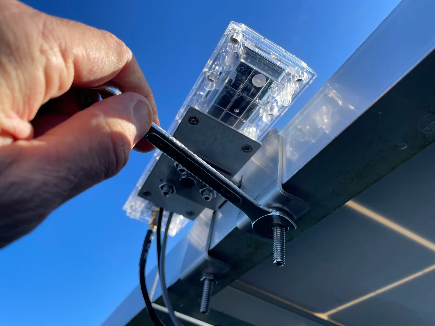
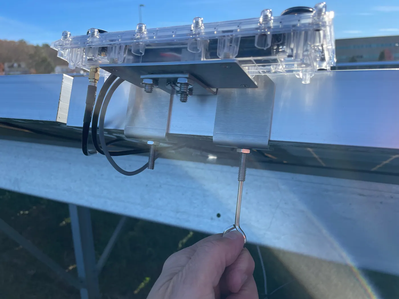
-
Ensure the bracket is flush to the module frame and in the same POA as the panel.
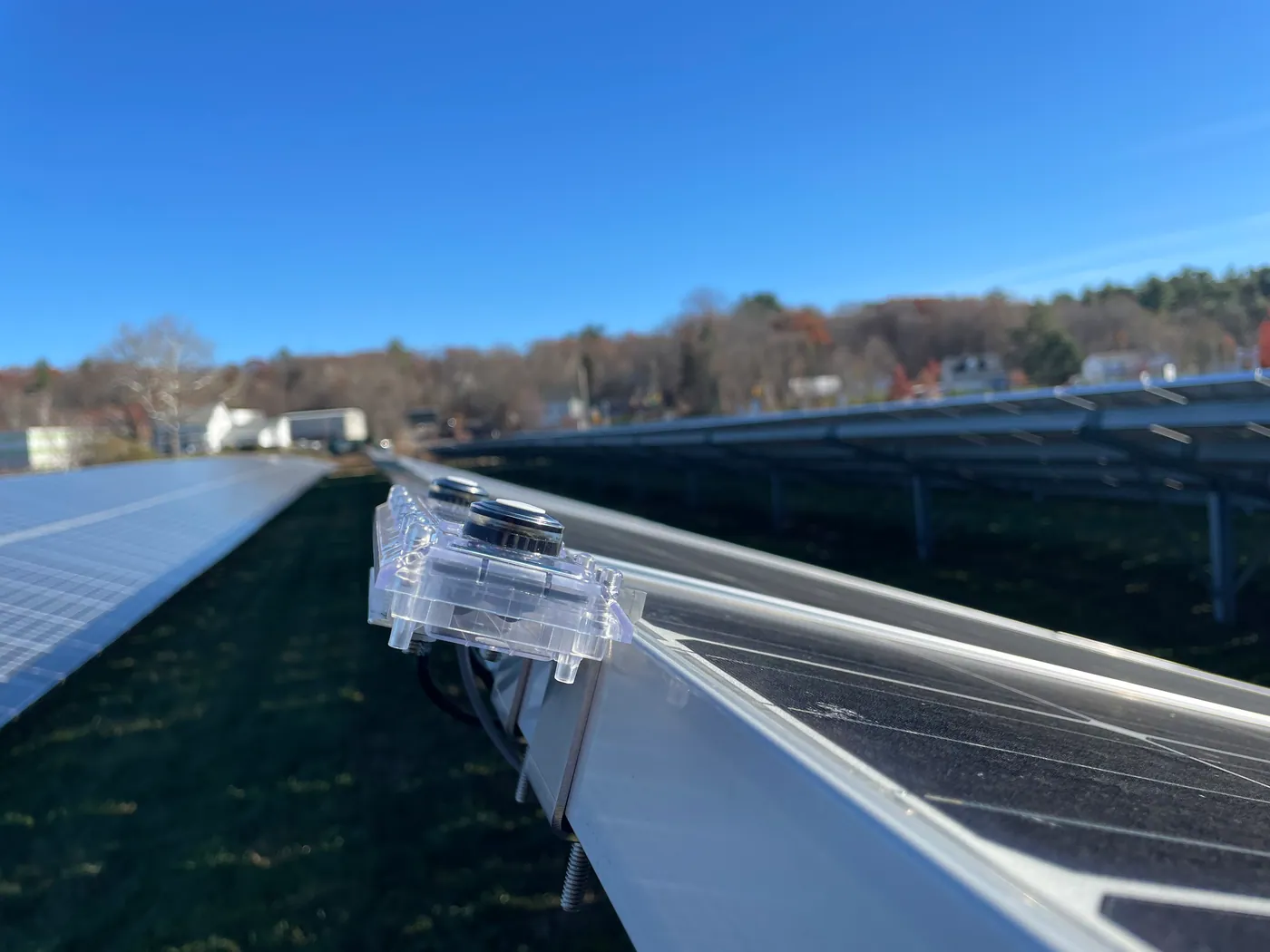
-
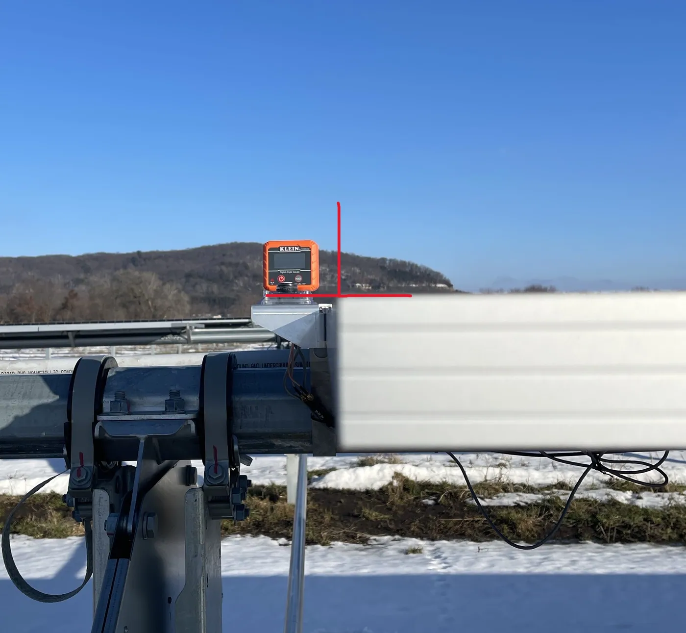
Check sensor levelness using the modules' Plane-of-Array, and use the bracket's set screws to fine-tune the angle so the sensors are perfectly aligned with the panel and the system's average north/south tilt.
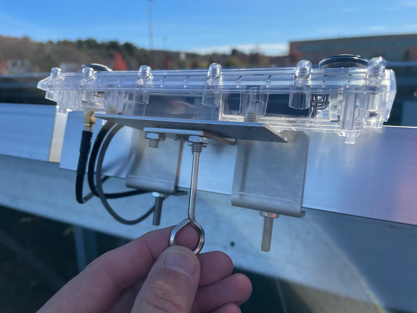
- For tracking and fixed tilt systems, use a digital level and ensure Deno's tilt in the north/south direction matches the panels'. It is best to stow the panels flat to check levelness. Ensure the north/south tilt of the Deno sensor matches the As-Built energy model average north/south tilt.
- On a single-axis tracker, if the quality of the Deno-to-panel mount is poor, the sensor can lean slightly off the module resulting in inaccurate readings.
3. Mount the Deno Sensor Antenna
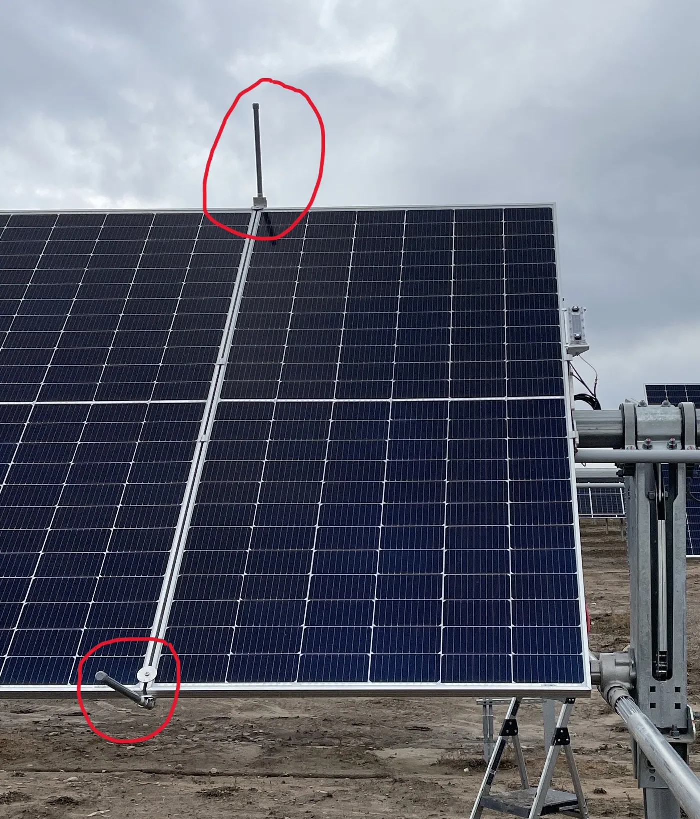
Mount the Deno sensor antenna with the provided hardware. Please read the full article on Denowatts Antenna Installation for detailed antenna installation instructions. In summary, the Deno sensor antenna should be mounted with:
-
Vertical Orientation.
-
Continuous Line-of-sight with the gateway's antenna and within 1200 feet.
-
1 module distance from the Deno sensor. (to prevent shading)
-
4-6 feet away from other antennas.
-
Even if the gateway antenna cannot be seen, as long as there are no obstructions between them, the Deno sensor will communicate reliably over 1/4 mile.
-
Look out for cell towers - if a cell tower is nearby, the Deno sensor should be mounted very close to the gateway to reduce radio interference.
4. Verify Sensor Data
Please verify that the Deno sensor's data is being reported reliably to the gateway via the Mobile app or the Gateway LCD. Check that irradiance, temperature, and radio strength (40-60rssi) are reporting acceptable values.
5. Mount Auxiliary Sensors
Mount the back of the module temperature sensor (Tbom) and any auxiliary pyranometers.
TBOM - Back of Module Temperature Sensor
See the full installation instructions for TBOM using the link or by navigating to the Auxiliary Sensor drop-down on the left.
- Must be at least 1 module in from the perimeter of the array (cannot be on a row at the edge of the array, or on a panel at the end of a row).
- Must be 24" from the module frame.
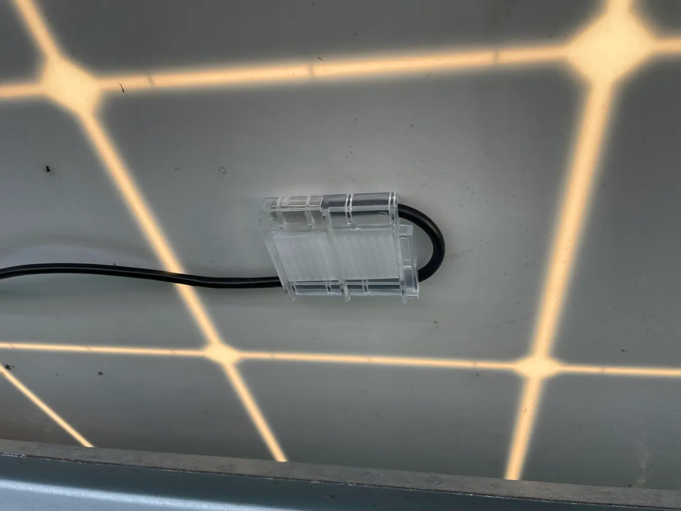
- The sensor tip must be mounted in the middle of a PV cell. Ensure the tip of the sensor is NOT in a gap between the cells
- Clean the application area before mounting.
- Ensure the TBOM lead is horseshooed around the plastic housing.
rPOA - Rearside/backside POA Pyranometer
See the full installation instructions for rPOAs using the link or navigating to the Auxiliary Sensor drop-down on the left.
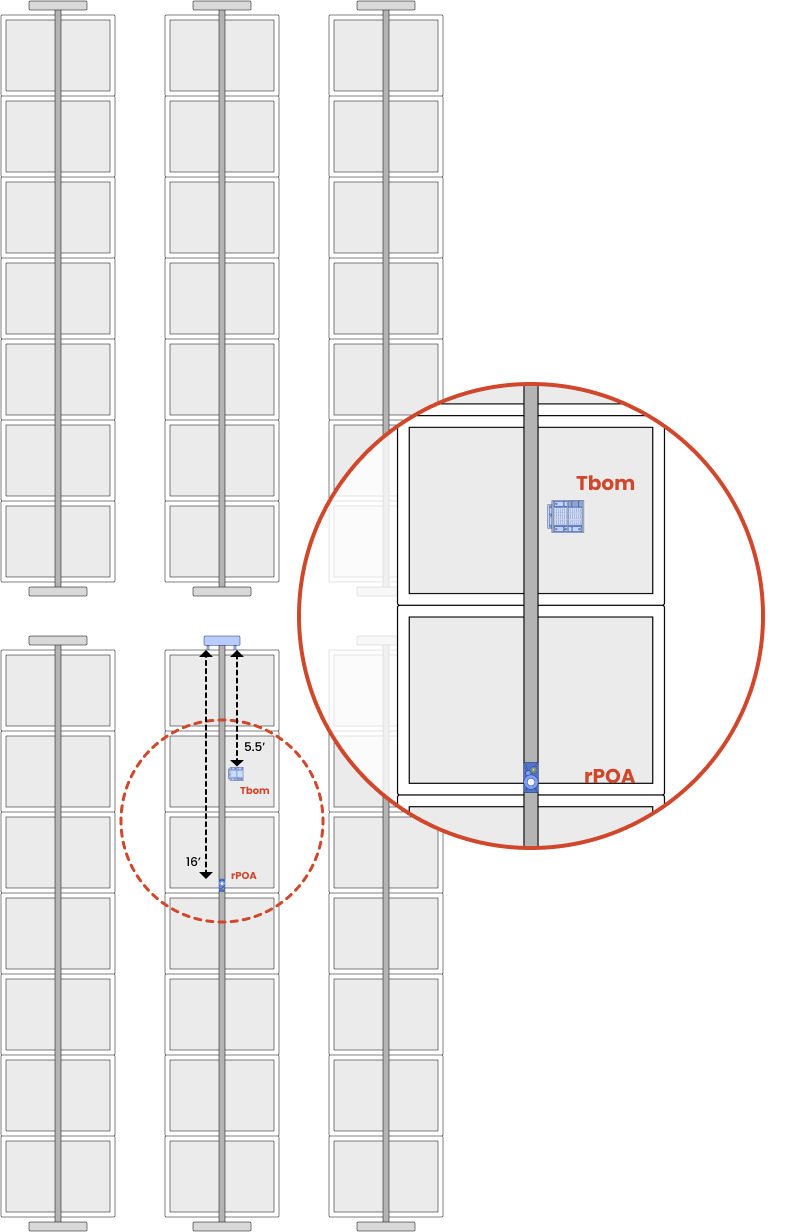
- Must be at least 3 modules in from the perimeter of the array (cannot be on a row at the edge of the array, or on a panel at the end of a row).
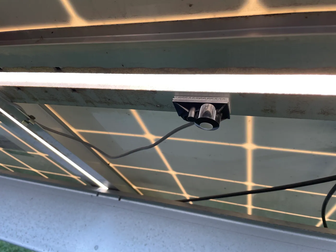
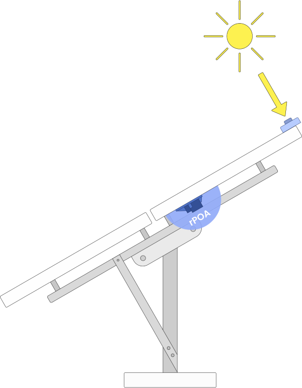
- Mount in the rear plane of the array. 1/2 to 2/3 up from the bottom edge of the total array
- Clean the application area before mounting.
Aux-GHI
See the full installation instructions for Auxiliary GHIs using the link or by navigating to the Auxiliary Sensor drop-down menu on the left side of the page.
- Ensure there is no shading from the Deno antenna.
- Ensure the bubble level is within the indicator's limits.
6. Wire-Management
Tidy up loose wires with zip ties, wire clips, and/or sun-bundlers. Ensure wires are securely attached to the module and kept away from moving tracker parts, sharp edges, and DC cables.
7. Verify and Take Pictures
Verify
Use the mobile application to verify the Deno sensor data post-install. If you verified prior to installation, there should be no surprises. Denowatts' support can also assist with verification. It's best to have the DAS energized and connected to the internet. Contact us using the information at the bottom of the page and have your pictures ready.
-
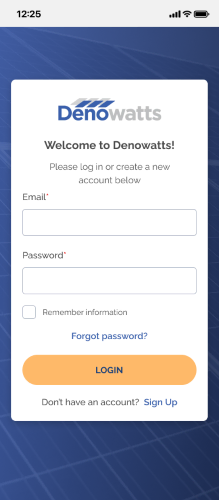
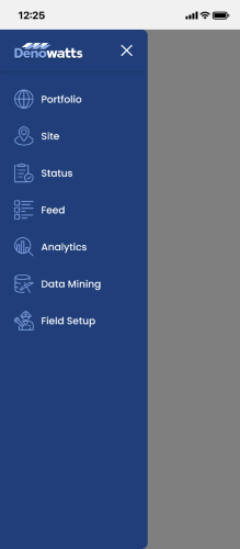
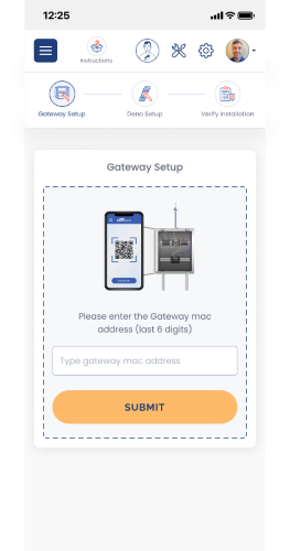
Sign on to the app, go to the Field Setup page.
 >>
>> 
-
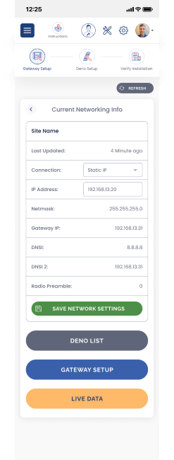
Enter the last 6 characters of the Gateway MAC address, then select Live Data or Deno List.
 >>
>> 
-
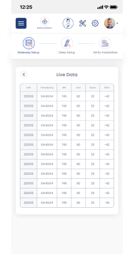
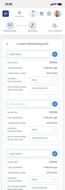
Check the Deno List and/or Live data, and ensure all Deno sensors installed recently are reporting to the gateway.
 >>
>> 
Pictures
Take pictures and mark up the drawings with the final Deno Sensor Location. A typical Denowatts installation requires the following picture documentation. Please upload to the app, Denobox, or send to support@denowatts.com in a .zip file.
-
Front side of the Deno sensor. Ensure the bracket is flush to the module frame, and the Deno Sensor is not in shade.
- Make sure the serial number is captured in the photo.
-
Deno Antenna. Ensure the antenna is at least 5 feet away from the Deno sensor.
-
Back of Module Temperature Sensor.
-
The rear-side pyranometer and its serial number.
-
An entire, open DAS enclosure that contains Denowatts Gateway.
-
Close-up of Denowatts Gateway.
-
Gateway Antenna. 4-6 feet away from other antennas.
-
Deno Sensor antenna to Deno Gateway Antenna line-of-sight (best you can).
Repeat the process for each Deno.
Fixed-Tilt Ground Mount Example
The antenna is far enough away to ensure the Deno Sensor is not shaded by it.
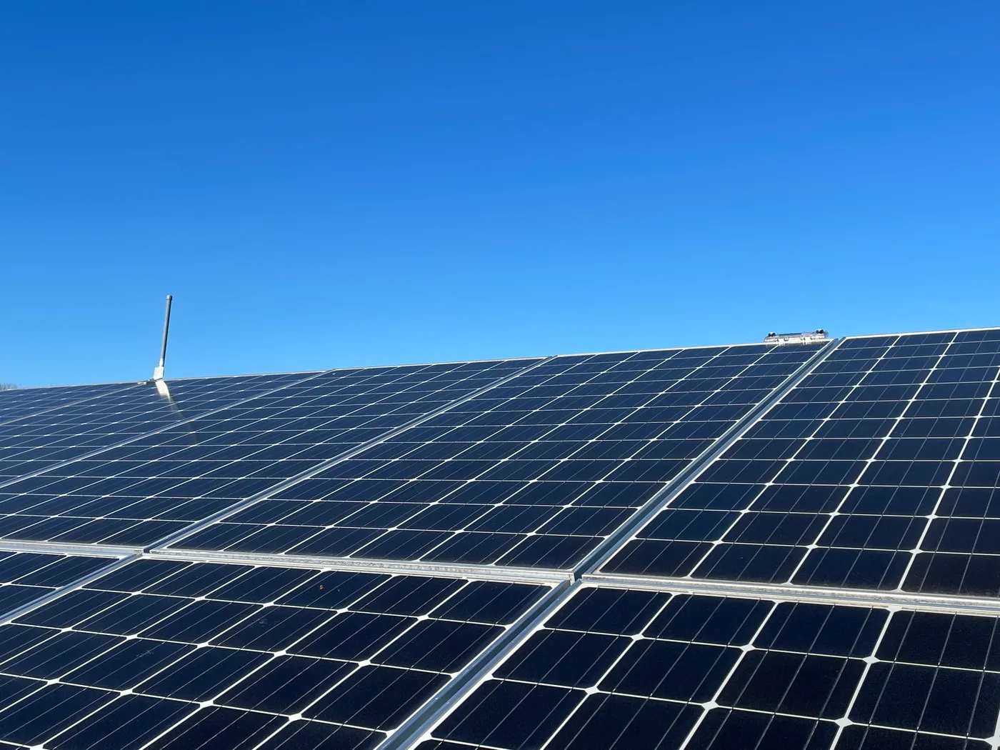
Deno Sensor is in perfect POA with the module
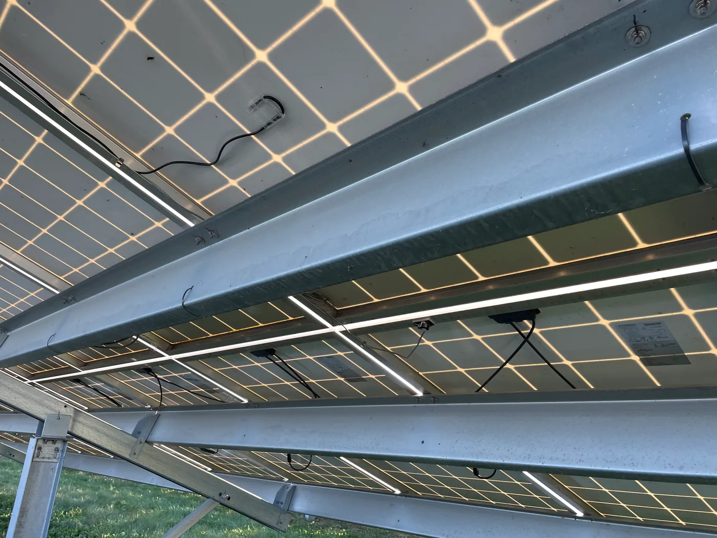
rPOA and Tbom are securely fastened, and wire management is tidy.
The back of the Module temperature sensor is in the middle of the PV cell, and the wires are horseshoeed around the plastic.
rPOA is mounted roughly 1/2 to 2/3 of the way up the back of the entire array.
Single Axis Tracker Example
In this image, you will see an example mounting position of a POA Deno Sensor on a tracker system. Try to mount the sensor as close to the torque tube as possible. 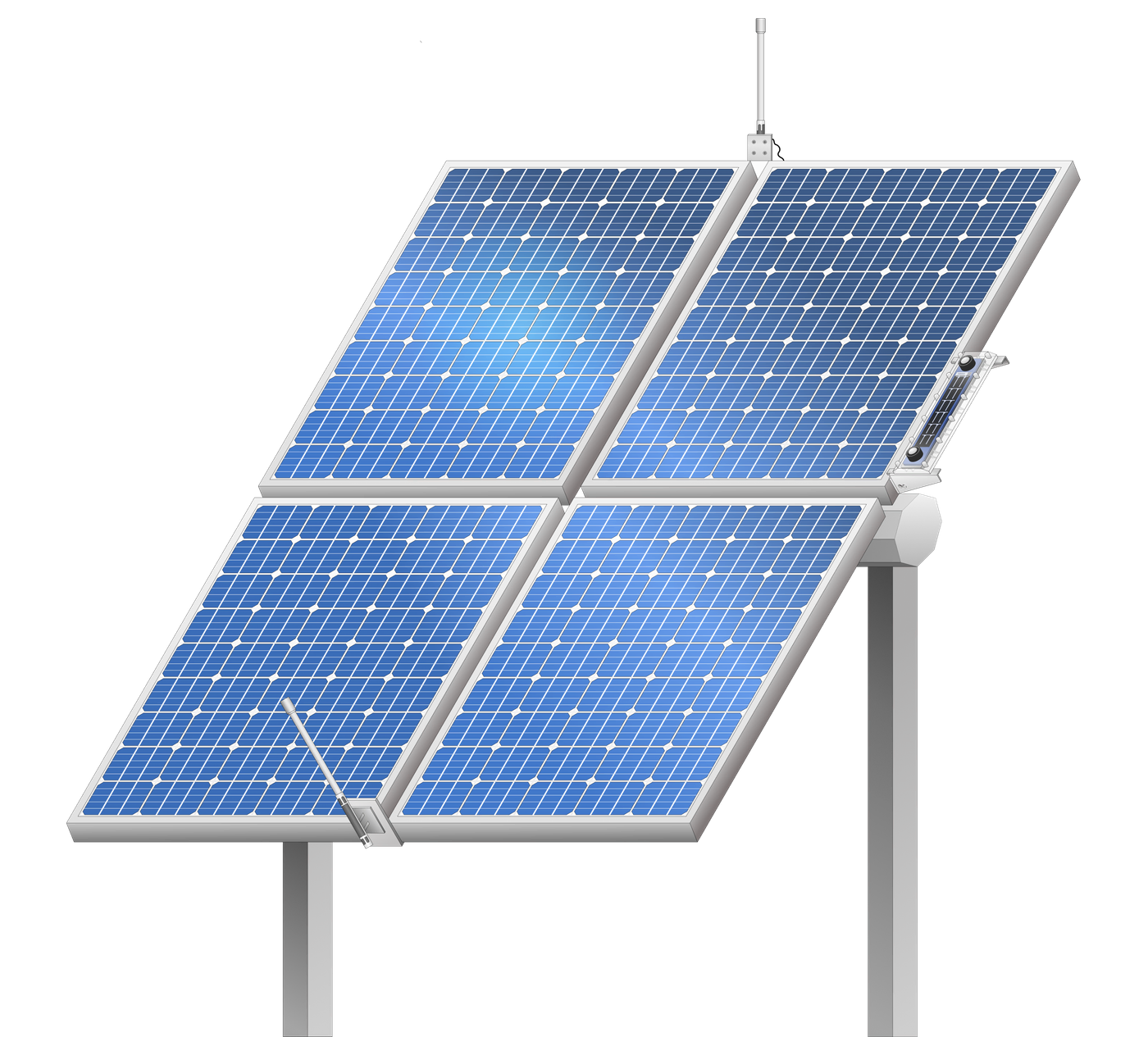
In this image, you will see an example of where to mount Auxiliary sensors compared to the Deno Sensor. Ensure the Deno Sensor is not mounted on an edge row of the tracking table, and that mounting sensors are several modules into the array.
- If rPOAs are mounted at the end of the row, the will not read a representative sample of the array.
Fixed Tilt Example
In this image, you will see an example of where to mount a POA Deno Sensor on a fixed tilt system.
- Top edge of panel.
- Antenna at least 5 feet away from Deno Sensor.
The same technique applies to Roof-tilt, Ground-mount, and carport fixed-tilts. 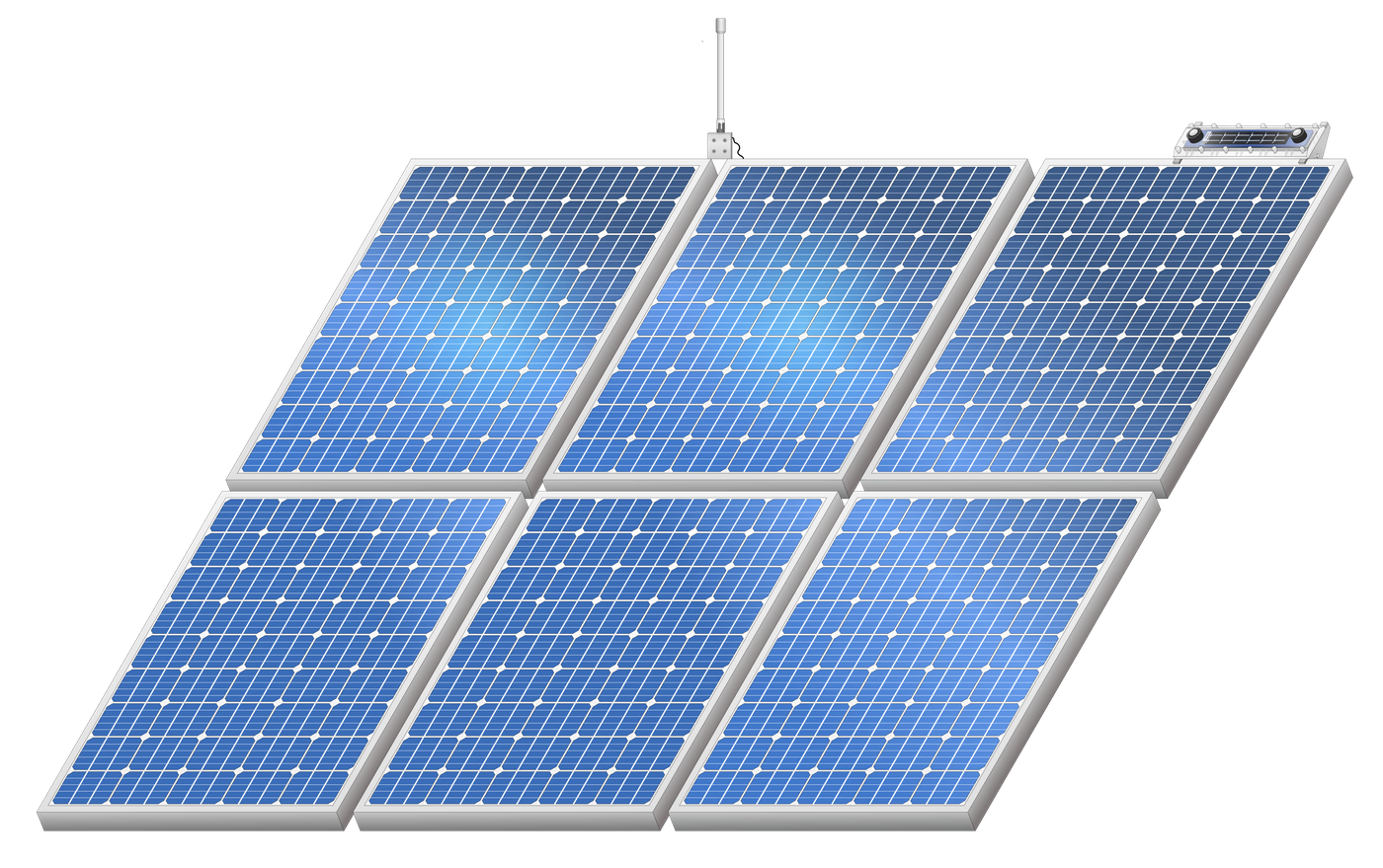
In this image, you will see that the rPOA is mounted 2/3rds up from the bottom of the array.
Please contact Denowatts to ensure the sensor and gateway locations are adequate, or if there are any questions, comments, or concerns:
- By Phone: 978.309.6688 x1
- Email: support@denowatts.com
Last updated on