
Overview
The first step in the installation process is to install the Gateway (G3) and Hub (H1). For full operation of the gateway, 12-24V DC power and internet access are required.
-
Download our Gateway + Hub installation and product cut sheets for a concise overview, including descriptions of the device's features and best installation practices.
***If there is no internet access, the Deno sensors will still communicate with the gateway once both the gateway and sensors have power. (Use the touch screen LCD interface to view their data). The gateway will store the Deno Sensor data until internet access is enabled, and then start backfilling the sensor data to Denowatts servers (~2-4 weeks, depending on the # of sensors reporting)***
Charge up the Deno sensors.
Before we dive into the Gateway, we want to make sure the Deno sensors are charged. The Deno sensors are self-powered and typically have no battery life when new out of the box. The Deno sensors must be charged to complete installation and verification.
If you charge up the Deno sensors before installing the gateway, by the time the gateway is installed, the Deno sensors will have enough charge. They should be ready to communicate with the gateway immediately once both are powered on.
There are two charging options:
- Place in direct, moderate sunlight for 30 minutes (will take more or less time depending on how sunny it is)
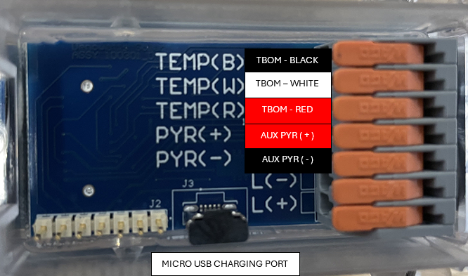
- Charge via Micro-USB cable from any power source.
- Locate The Micro-USB port on the back of the Deno, behind the clear removable casing
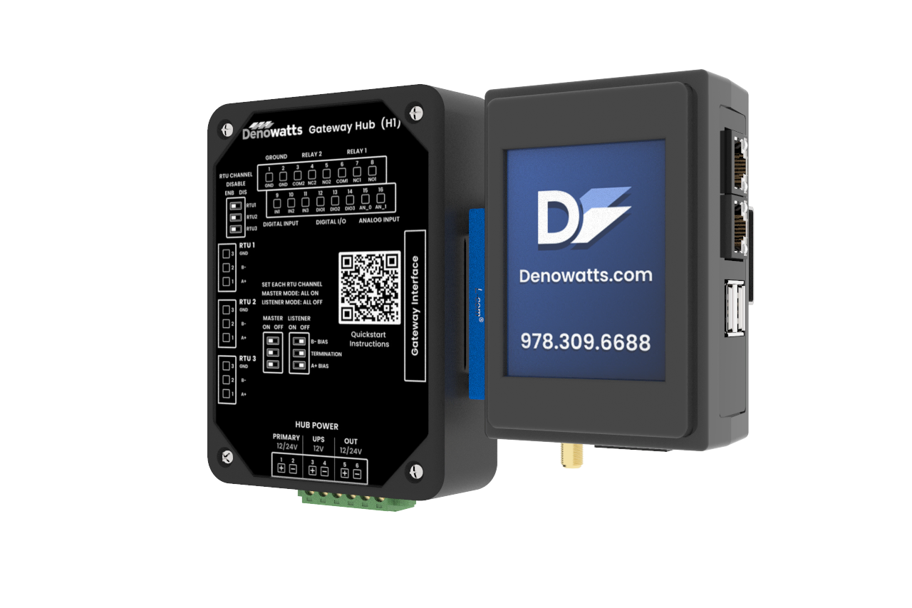
Denowatts Gateway (G3) + Hub (H1)
General G3 Information
The Denowatts Gateway and Hub are a receiver/coordinator for all Deno sensors. It is both a Modbus server that provides data to 3rd-party monitoring applications and a Modbus client that acquires data directly from local devices. As the central reporting location for the Deno sensors, the data is received, processed, and transmitted to cloud servers. All wires are landed in the Hub, both the DC power and the RS-485 serial. The Hub also contains built-in surge protection. The Hub is only required if serial modbus RS-485 connections are the only the means of connecting to field devices (versus Modbus TCP)
Working Space Requirements
-
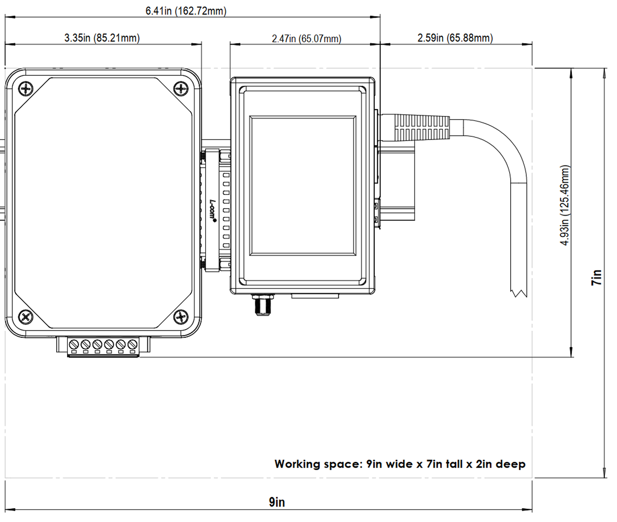
With wiring space considered, the optimized working space is 9" wide, 7" tall, and 2" deep.
- If a Denowatts modem is supplied, the space required is 10" wide by 8" tall
Connection Point Descriptions
***Please download the PRODUCT CUTSHEET for a more detailed product description. A summary is laid out below.***
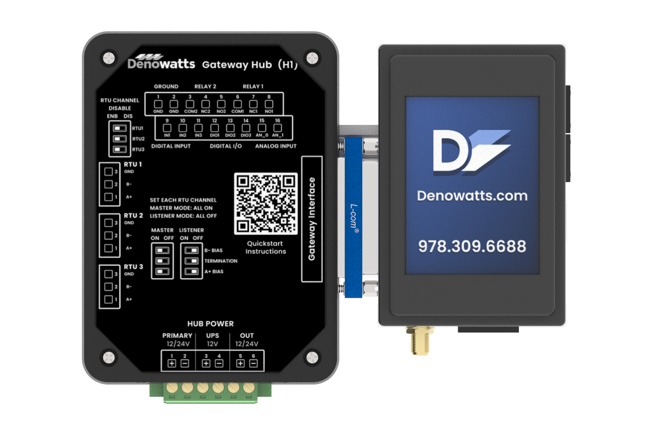
FRONT VIEW: The diagram below shows the front face of the Denowatts Gateway and Hub
-
HUB
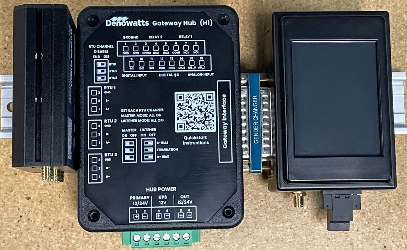
- The front cover of the hub contains detailed labels of landing points and their assignments. When a hub is supplied, all power and communication wires will land at the Hub.
-
GATEWAY
- The front contains a Touch Screen LCD interface to navigate the Gateways Menus (network information/configuration, and Deno Sensor Data)
BOTTOM VIEW: The diagram below shows the bottom face of the Gateway and Hub.
-
Hub:
-
Cut-outs for serial RS-485 wires.
-
Detailed view of the terminal blocks for landing power wires described above in FRONT VIEW.
-
-
Gateway
-
Threaded, male RP-SMA connection port for the Gateway Antenna.
-
Auxiliary power connection to power the Gateway if no Hub was required for the project.
-
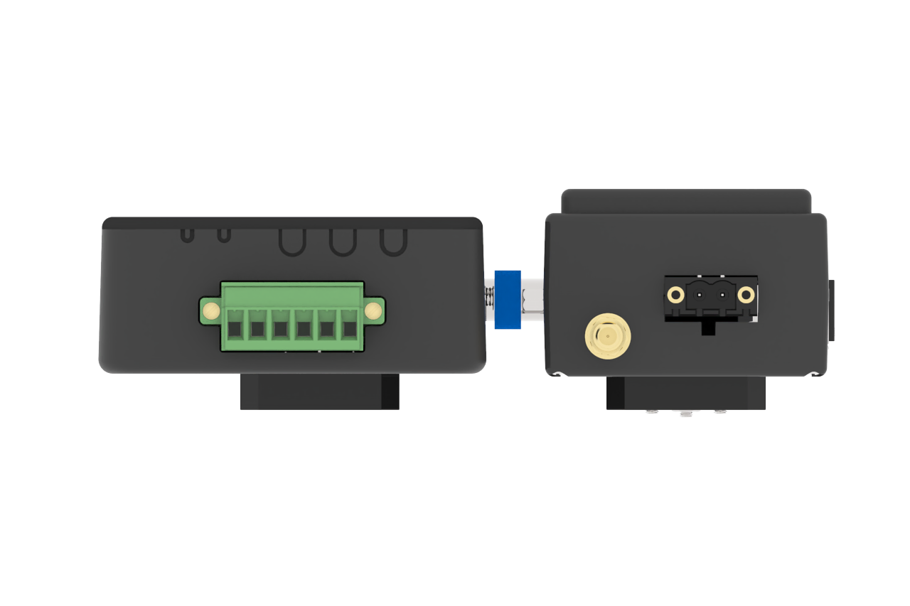
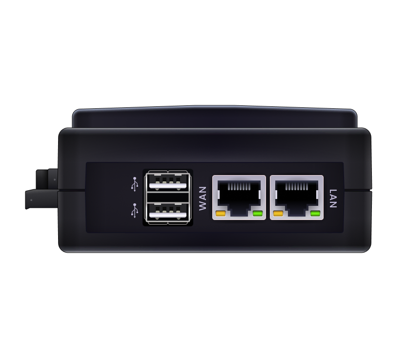
SIDE VIEW: The diagram below shows the Gateway's side view.
- USB Ports: for future direct local data downloads from the device
- WAN - Unused. (Plugged in only to a Denowatts cell modem if ordered)
- LAN - plugs into the site's existing LAN (local area network)
ASSEMBLY VIEW: PicturedEw is a Denowatts assembly containing (left to right) the RUT 241 cell modem, Hub (H1), and Gateway (G3).
Please contact Denowatts at any point while reading this guide with questions, comments, or concerns:
- By Phone: 978.309.6688 x1
- Email: support@denowatts.com
- Check out the Denowatts Support Center for more articles that dive deeper into our methodology and software.
Last updated on