
GHI Deno
Sometimes, a stand-alone GHI Deno sensor is included with tracking systems. GHI stands for Global Horizontal Irradiance, and as the name implies, this sensor will be mounted in a fixed position, perfectly flat in both X and Y Directions. Follow the steps below.
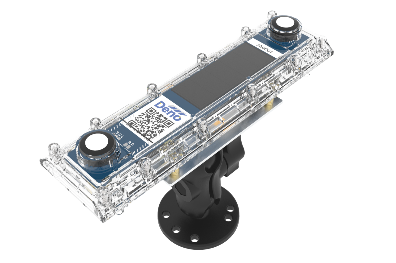
1. Move to Mounting Location
In most cases, the GHI Deno sensor is installed at the same equipment pad as the Denowatts gateway.
2. Mount the Deno Sensor
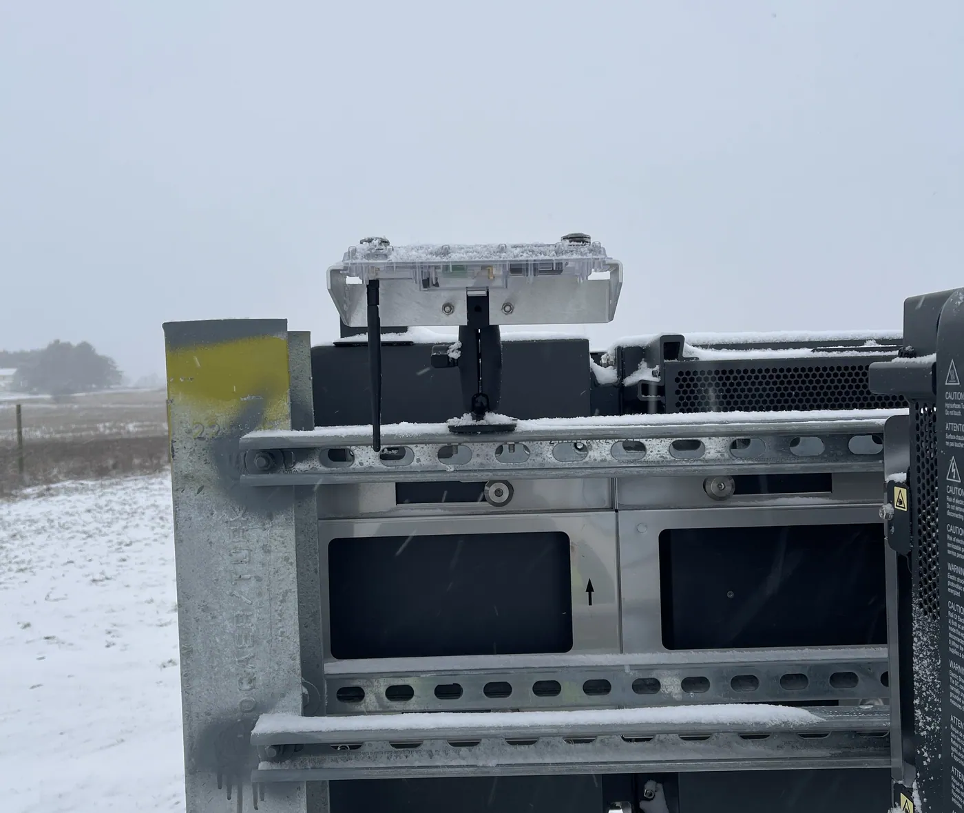
Please mount the sensor in a location where it will not be shaded by nearby equipment. Using the supplied hardware, mount the sensor to an appropriate location on the rack (typically on unistrut, on a pole, or a pile). Ensure the double-ball joint bracket is tight.
3. Verify Levelness (x and Y Directions)
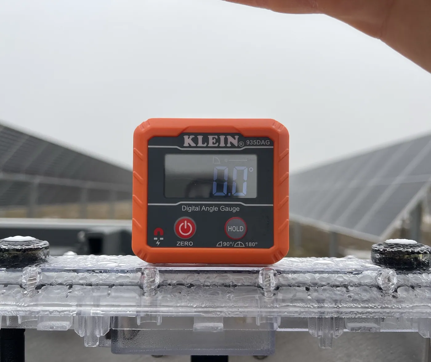
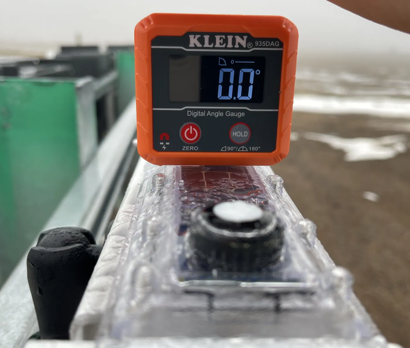
Use a digital level (or angle finder) to ensure the sensor is not tilted in either the X or Y direction. (see example image below)
3. Mount the Deno Sensor Antenna
Given that, in almost all cases, the GHI Deno sensors are mounted very close to the Deno gateway and its antenna, the GHI sensor already comes with a smaller antenna attached to the back of the Deno sensor. (see example image below)
4. Verify and Take Pictures
Verify
Use the mobile application to verify the Denos data post-install. If you verified before installation, there should be no surprises. Denowatts' support can also assist with verification. It's best to have the DAS energized and connected to the internet. Contact us using the information at the bottom of the page and have your pictures ready.
-
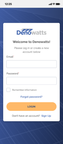
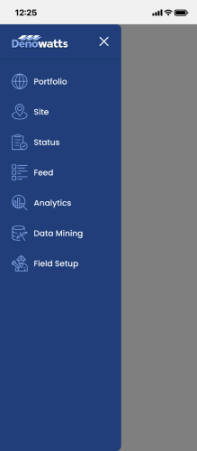
Sign in to the app, go to the Field Setup page.
 >>
>> 
-
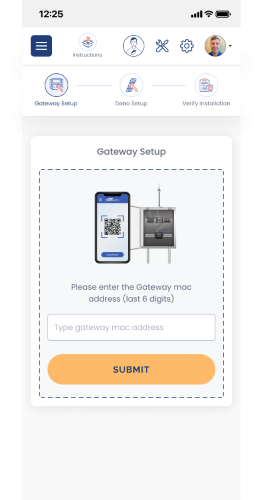
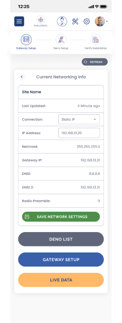
Enter the last six characters of the Gateway MAC address and then select Live Data or Deno List
 >>
>> 
-
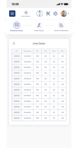
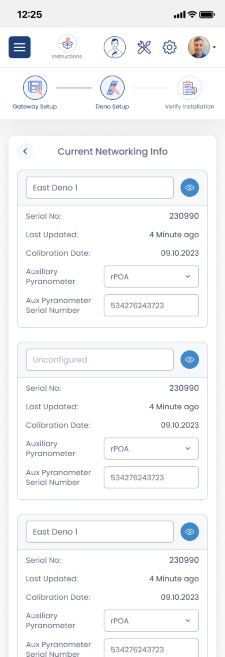
Check the Deno List and/or Live data, and ensure all Deno sensors installed recently are reporting to the gateway.
 >>
>> 
Pictures
A GHI's documentation is a bit easier than a POA, as there is less to document. Please take the following pictures and upload them to the app or send them to support@denowatts.com
- GHI leveled in the X direction.
- GHI leveled in the Y direction.
- GHI antenna and wire management (if applicable).
- GHI antenna-to-gateway line of sight.
Example Installation
Please contact Denowatts to ensure the sensor and gateway locations are adequate, or if there are any questions, comments, or concerns:
- By Phone: 978.309.6688 x1
- Email: support@denowatts.com
Last updated on