
2. Antenna
The next part of the gateway installation is mounting the gateway's antenna. Please follow the instructions below to ensure success on this critical aspect of the Denowatts installation process.
Gateway Antenna Mounting
Now that the Gateway is securely mounted and connected to the DAS, the next step is installing the antenna. The antenna is essential in the Denowatts system because the sensors communicate with the Gateway via radio frequency (900 MHz Zigbee protocol). The antenna enables this communication process.
Please read the full Denowatts Antenna Placement article. This article provides in-depth information on installing the Denowatts antenna system and what we have learned over the years. It is pretty simple once you get the gist, but there are a few small things that can make a significant impact. We will go through the steps and considerations for the gateway antenna below.
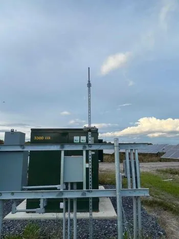
Installation Steps
The first antenna installed on the system is the gateway antenna. This gateway antenna is installed where the Denowatts gateway is located, which is typically at the central pad within the main DAS enclosure. Follow the steps below for a proper Deno Gateway antenna installation:
-
Scope out a location: Look for a location where the Deno antenna will be atleast 4-6 feet away from other antennas on the DAS equipment rack, but within the range of the 15' cable provided. Think about where the Denos will be and whether line of sight will be achieved.
-
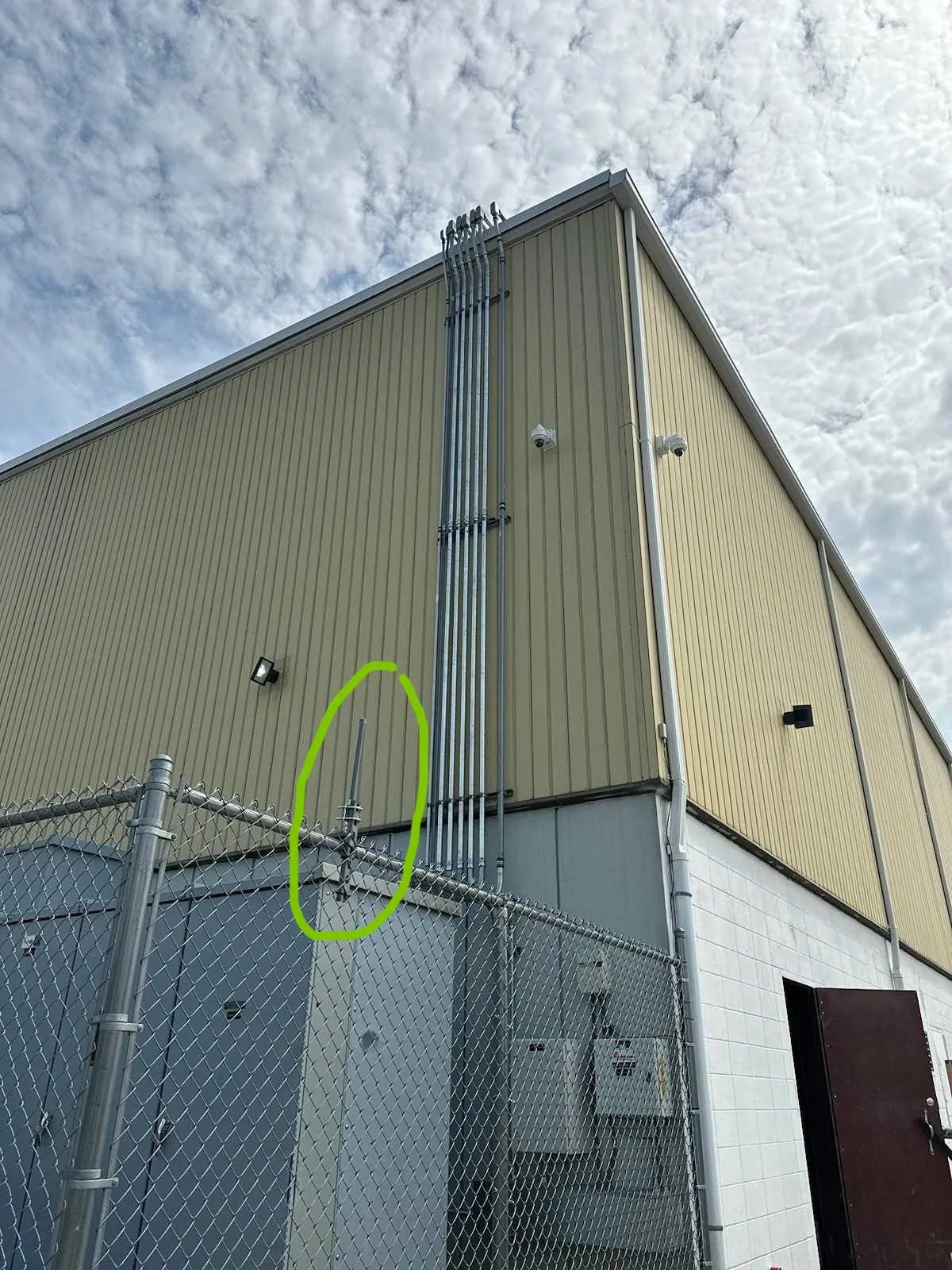
Install Uni-Strut: Mount a piece of strut/conduit vertically, secured to the existing DAS rack, close to the enclosure where the Denowatts gateway is installed (see the example image above). Ensure the GHI or other nearby sensors are not being blocked/shaded (e.g., other Denos). The strut will ensure the gateway antenna has its unique location away from other antennas. Two items to note:
- The top of the pole should be about 8 feet above the ground.
- The higher the antenna is mounted, the better the communication with the Deno sensors in the array will be.
-
Mount the Antenna: Mount the antenna vertically to the top of the pole using the two U-brackets, and tighten the bolts appropriately.
-
Connect Cable to Antenna: Connect the 15' coaxial cable to the antenna using the threaded connection point, finger-tight.
-
Run Cable into Enclosure: run the coaxial cable through any existing cable glands in the enclosure or carefully create a new punch-out on the bottom for a new cable gland.
-
Connect Cable to Gateway: connect the RP-SMA screw connector to the Denowatts gateway and tidy up the wires with zip ties or sun-bundlers. Be sure there are no tight radii or loose loops.
- Caution: do not make punch-outs on the side or top of the DAS enclsoure
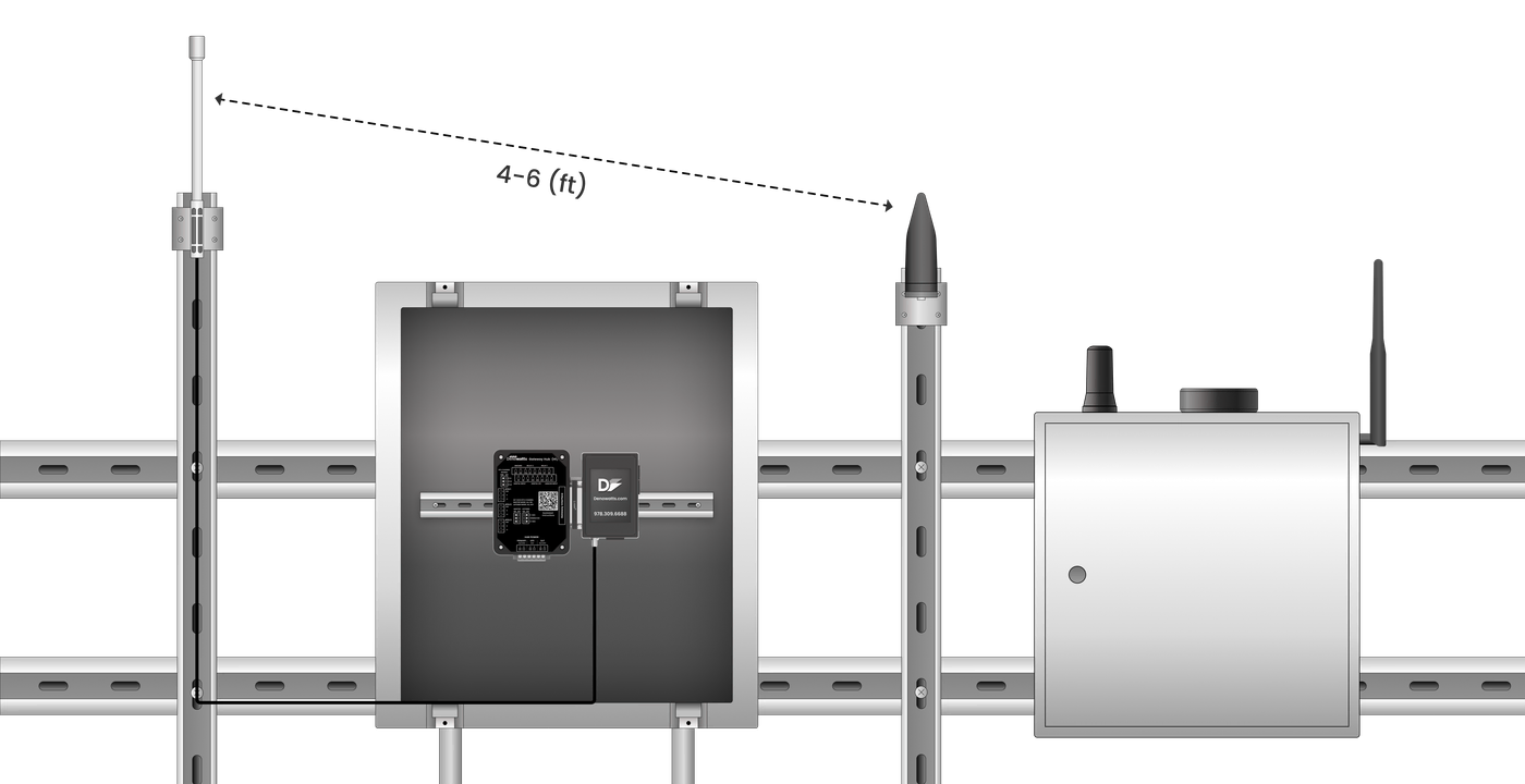 For best results, the Deno Antenna must be mounted 4-6 feet away from other antennas on the DAS rack.
- Cellular Antennas
- Utility Meter Antennas
- Tracker Controller Antennas
- Tracker GPS Antennas
Creativity: sometimes you have to get creative, especially in situations with alot of antennas in a small space. Where should the Deno gateway antenna go here? 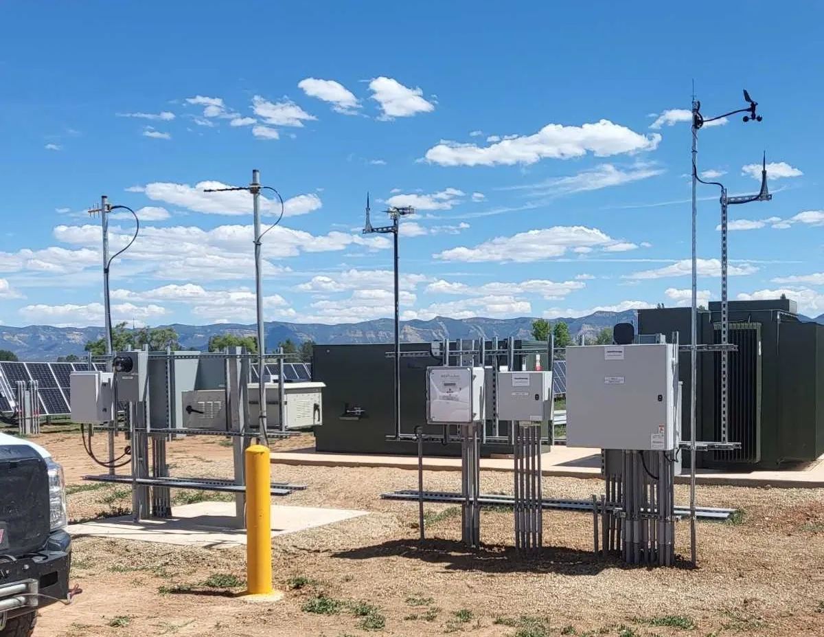 Answer: Mount a vertical piece of strut in the middle of the right DAS rack so the antenna is 4 feet above the rack, and equidistant between the antennas on the left and right.
Example Scenarios
!! If there is a cell tower next to the solar system, Deno sensors must be mounted as close to the gateway as possible. Cell towers create radio interference with the Deno wireless network !!
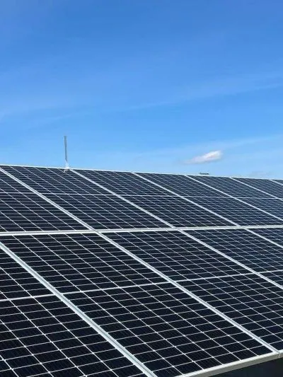
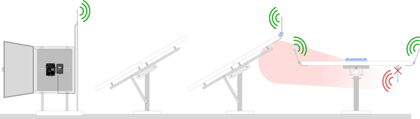 2D Cross Section of the Antenna system is depicted above. Notice how the antennas are installed at the top edge of the panel to achieve the best, continuous line of sight to the gateway.
Tracker
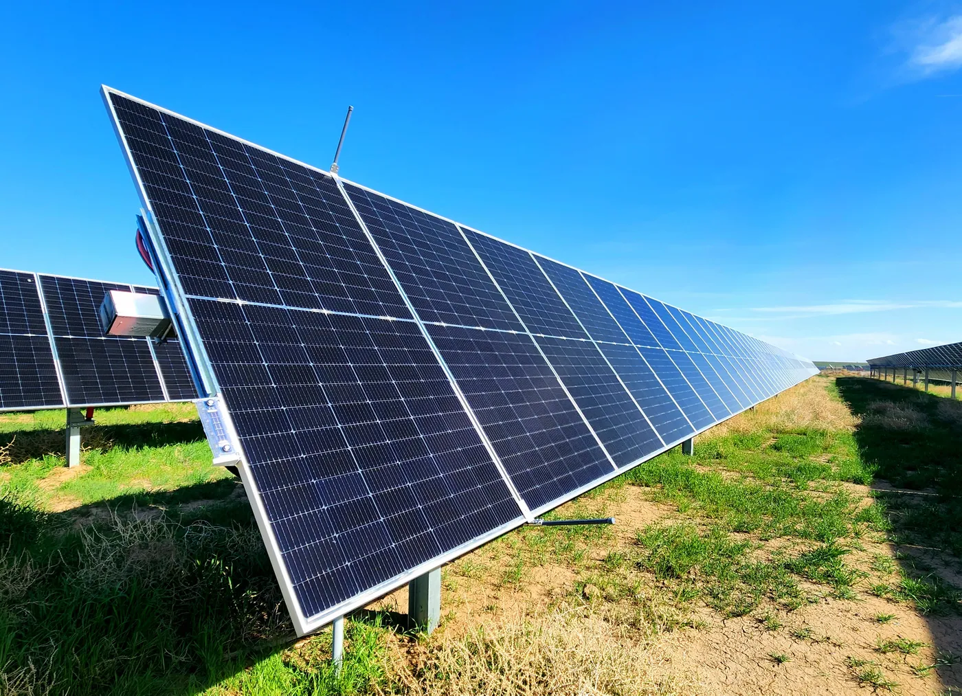
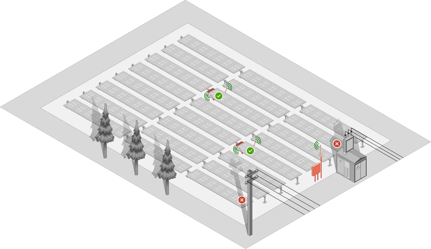 Notice how the gateway antenna is installed high on a pole in a vertical orientation to maintain a line of sight to the tracking array. Notice that there are two antennas for each POA sensor, with one mounted on each edge of the tracking table. This ensures a continuous line of sight throughout the day as the array tracks the sun.
Fixed Tilt
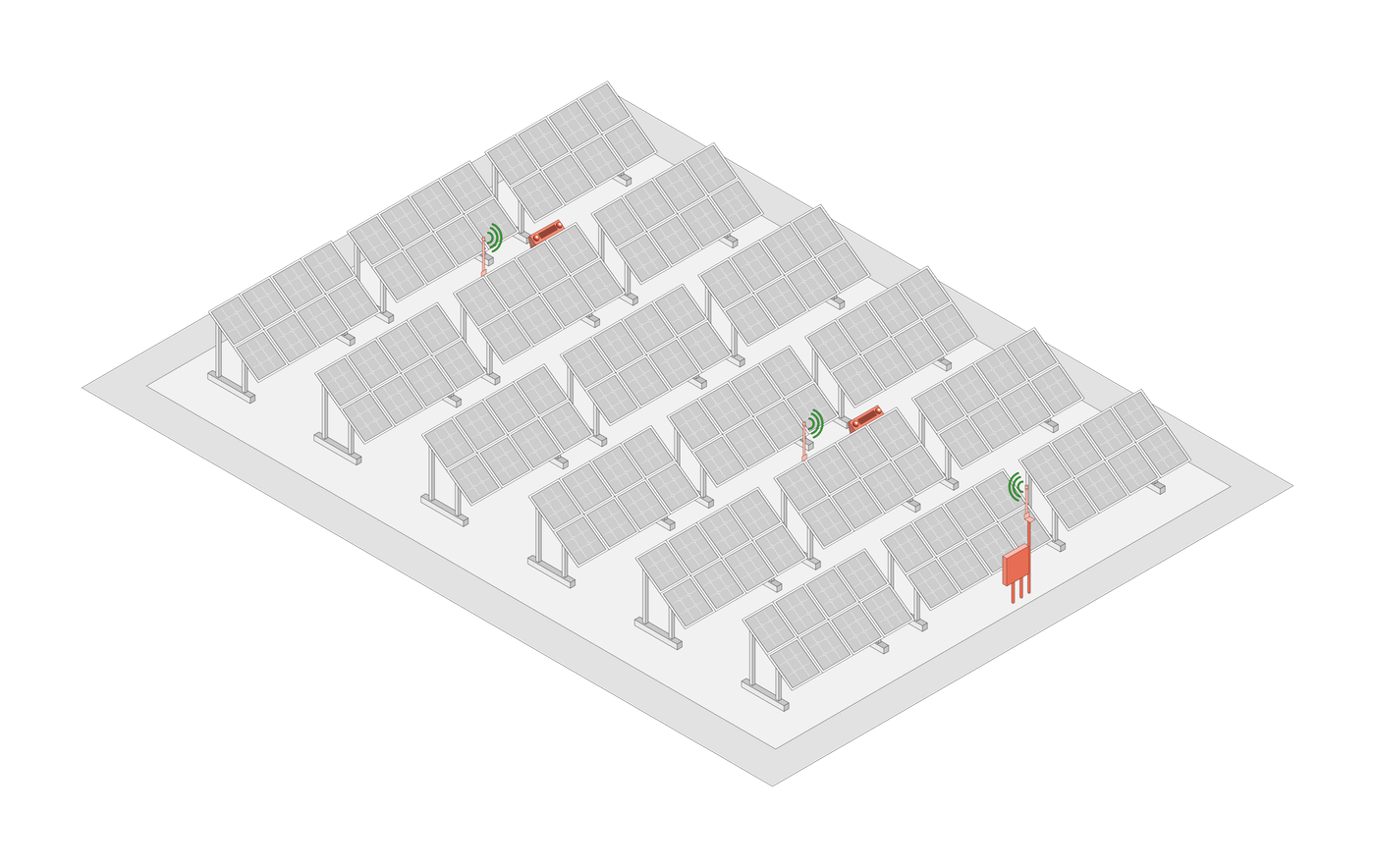 Notice how the gateway antenna is installed high on a pole in a vertical orientation to maintain a line of sight to the tracking array. Notice how the Deno antennas are installed far enough away from the sensor to avoid shading, and mounted on the top edge of the panel for the best line of sight.
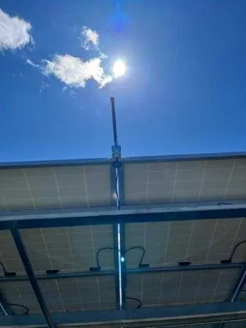
Roof Top
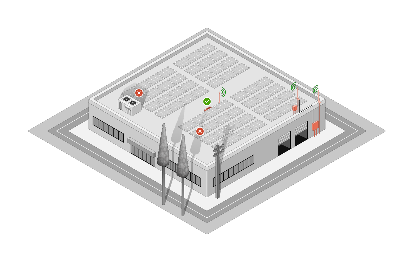 Notice how the gateway antenna is installed on the roof and not on the side of the building. This creates a line of sight between the antennas. All antennas are also mounted vertically.
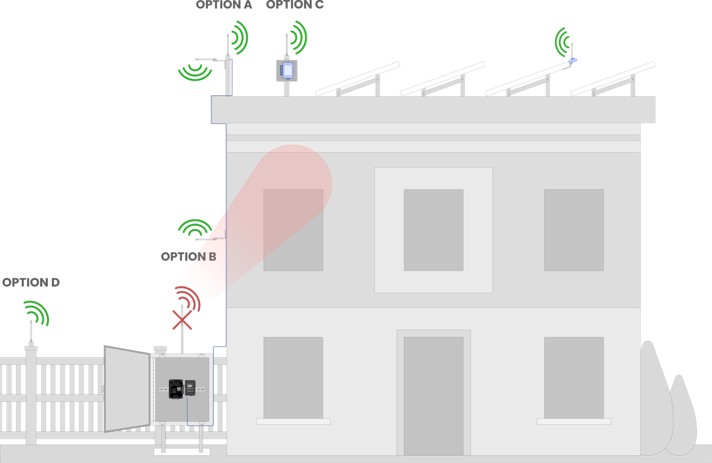
Option A: An antenna with an extender cable can be run up the side of the building to the rooftop to create a line-of-sight between the deno and the gateway antennas
Option B: The Deno Gateway antenna is extended up the side of the building, mounted horizontally, 3' off the wall, and the Deno Sensor antenna is brought to the edge of the building to create a line-of-sight with the Deno Gateway antenna.
Option C: The Gateway can be mounted in a NEMA 4 enclosure on the rooftop to create a line-of-sight between the antennas.
Option D: The Deno gateway antenna is extended as far away from the building as possible. Ideally, the Deno sensor is placed on the side of the array where the gateway is on the ground, and its antenna is extended to the edge of the building as far as possible.
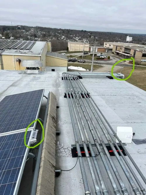
With the gateway and antenna properly installed, it's time to move on to the next step!
Please contact Denowatts at any point while reading this guide with questions, comments, or concerns:
-
By Phone: 978.309.6688 x1
-
Email: support@denowatts.com
-
Check out the Denowatts Support Center for more articles that dive deeper into our methodology and software.
Last updated on