
Equipment Locations
1. Check with your Team
Locating and orienting Deno sensors within the project site is critical to a successful installation. Improperly located or mounted sensors will require correction, possibly by a second site visit. If your design team has not yet provided a location plan, please consult with them first. Denowatts can assist with this process as well.
If your engineering team cannot provide sensor location information, please look at the PV array drawings and civil plan sets to get a basic idea of the site layout and where to place the hardware.
- Deno sensors should be located in the sunniest parts of the array, with at most a 1/4-mile line of sight to the Gateway antenna.
- If the array is not perfectly flat, it is extremely important to ensure the Deno sensors are on rows with a tilt that best represents the array.
- For larger sites using more than one Deno sensor, the sensors should be distributed to representative locations. For tracker sites, ensure Deno sensors are located in different rows and, if possible, on different motors.
Below is an example map/plan of proposed Denowatts equipment locations: 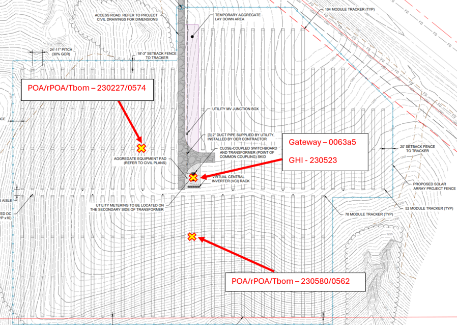
2. What to Consider
If you are tasked with determining a location, start to think about the following:
-
Equipment Pad Locations
- Is the gateway(s) in a central point for the radio transmissions from the sensors on site?
-
Antenna Considerations
- Are the Deno sensor antennas and the gateway antenna within 1200 feet? Do they maintain line-of-sight throughout the day?
- Obstructions between antennas (such as other solar modules, chain link fences, and roofing) can substantially reduce the effective transmission distance.
- If you are using a tracker system, are you using dual antennas to ensure at least one antenna is always line-of-sight with the gateway antenna?
-
Site Size, shape, and Terrain
- How many different POAs are the modules in on this site? How many Deno sensors are included?
- Is this a tracker or a fixed tilt system?
- Where are the sunniest locations on the array?
- Are there shading impacts that should be avoided?
- Is there a lot of undulation or variation in the site's grade?
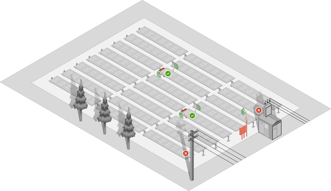
Example: Single-axis tracker with two Deno sensors.
The Denowatts Gateway is placed on a nearby equipment pad in the weatherproof DAS enclosure. Deno sensors are placed on distributed tracker rows to avoid shading from obstructions such as trees and other equipment. The antennas maintain a line of sight throughout the day, and the gateway antenna is mounted vertically as high as possible on a piece of unistrut.
3. Additional Placement Articles
Denowatts provides more in-depth articles on this process for further understanding. These are located in our support center. Direct Links are below.
- Sensor location and placement guide
- Antenna Placement and Installation Guide
4. Contact Denowatts
Please contact Denowatts to ensure the sensor and gateway locations are adequate, or if there are any questions, comments, or concerns:
- By Phone: 978.309.6688 x1
- Email: support@denowatts.com
Last updated on