
G2 Gateway
This hardware was discontinued on August 1st 2025
Legacy - G2 Gateway
General G2 Information
The Denowatts Gateway is a receiver/coordinator for all Deno sensors. It is both a Modbus server, providing data to 3rd party monitoring applications, as well as a Modbus client, acquiring data directly from local devices. As the hub for the Deno sensors, data is received, processed, and transmitted to cloud servers. 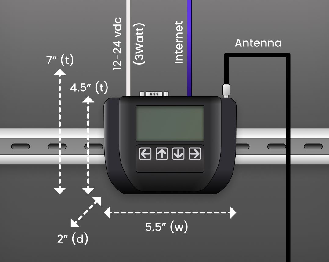 The diagram above shows the front face of the Denowatts G2 Gateway. Note the LCD screen and push-button interface. The back face includes a DIN-rail mounting clip. The required dimensions are also noted.
 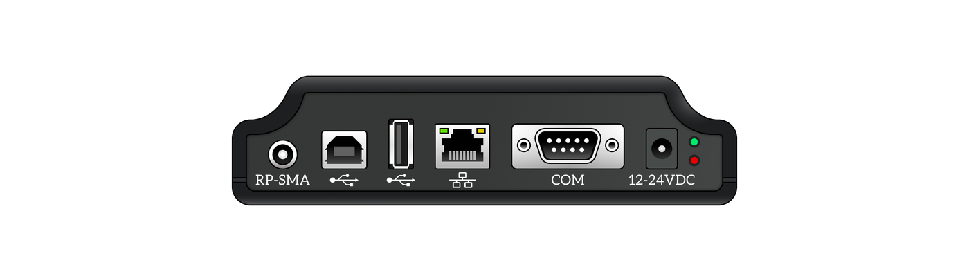 The second diagram shows the top face of the gateway, where the necessary wires and cables are connected. Note the following connection ports from left to right:
- Threaded Antenna port (RP-SMA)
- USB Type B
- USB Type A
- Ethernet port (cat5, RJ45)
- Serial Comms Port (for Denowatts modbus RS-485 adapter)
- 12-24V barrel jack power input
- Power Status Light
This first page details the physical installation of the gateway device.
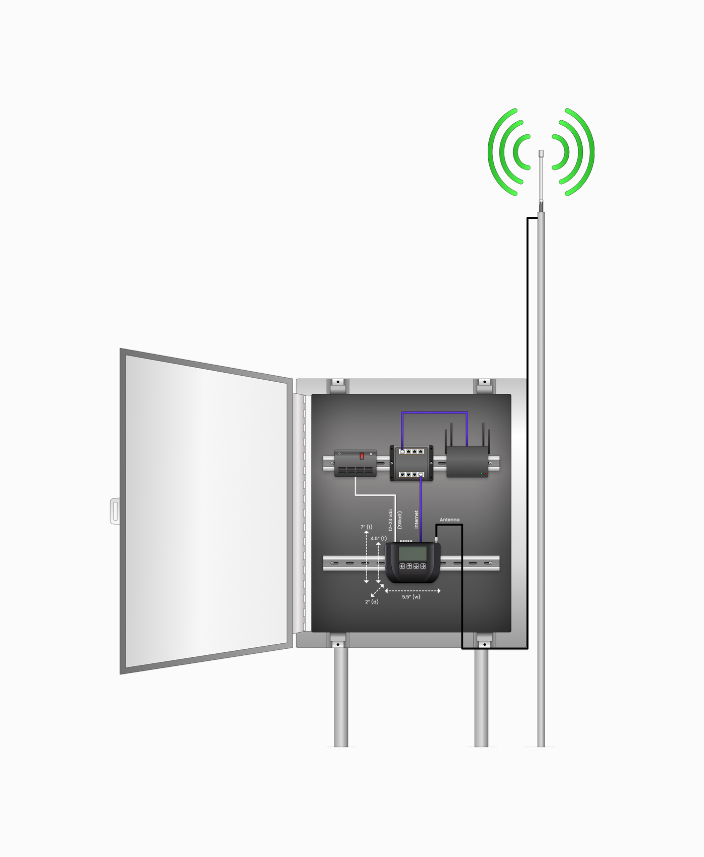
The gateway must be installed in a weather-proof (NEMA4) enclosure, typically the main DAS cabinet, and requires:
- 12-24VDC power supply (the gateways draw ~3watts).
- Internet access (LAN via RJ45 cable).
Installation Steps
-
Mount the gateway on available DIN-rail space.
-
Connect 12-24VDC power to the gateway using the barrel-jack connector and the existing power supply within the enclosure.
- If there is a UPS onsite (uninterruptible power supply), wire up the Denowatts gateway so that it will be backed up by battery power in the event of a grid outage.
- Verify the green power status light is on (it will illuminate immediately).
- The LCD screen may take up to 30 seconds to display.
-
Connect to the network switch within the enclosure using the provided Ethernet cable.
- Verify Ethernet status lights are operating (if network is configured).
- The proper status lights should be: Solid green (link), Blinking Orange (data transmission).
-
Connect the RS485 Adapter to the RS485 loop with the site's main production meter (if meter comms are modbus RS-485 and not modbusTCP).
- Red to (+), Black to (-), White to (G)
-
Connect Antenna - see the next page for full instructions.
-
Initial Denos and Check the gateway LCD Screen for Deno sensor communication
Sensor Comms Check
-
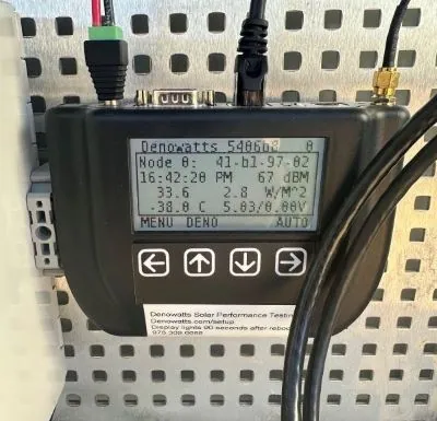
On a G2 gateway, the device's home page will display Deno data. As shown below:
-
Press the button underneath the "Deno" text to scroll through the number of "nodes" checking into the current gateway. The count starts at node 0.
- The screen will display a timestamp, and other metrics that the Deno is reporting in to the gateway.
-
Example Images
Full DAS Enclosure:
The Denowatts gateway is in the bottom right quadrant of the DAS box.
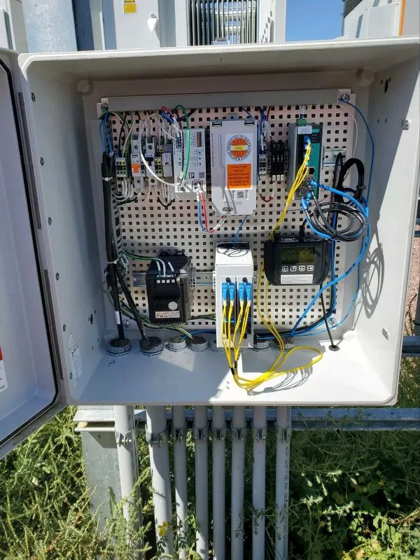
Close Up:
Notice how the cables have plenty of space and are not bent sharply.
Please contact Denowatts at any point while reading this guide with questions, comments, or concerns:
- By Phone: 978.309.6688 x1
- Email: support@denowatts.com
- Check out the Denowatts Support Center for more articles that dive deeper into our methodology and software.
Last updated on