
Document
Congratulations! You have completed your Denowatts Hardware Installation! Now it is time to document your handiwork.
Denowatts Equipment Map
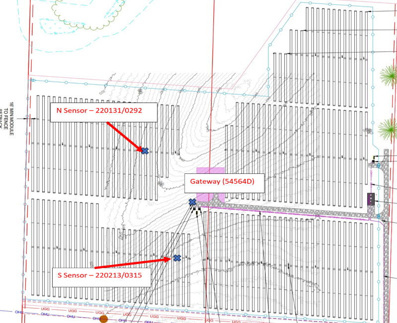
Please mark up an array layout as-built drawing with the Denowatts equipment locations. This will help future O&M teams locate sensors for calibration or maintenance purposes. Please include:
- Each POA Deno sensor's location in the array.
- The pad at which the Denowatts Gateway and GHI sensor are located.
See the example Deno Equipment Location Map Below:
Pictures
Please upload the required pictures to the Denowatts Mobile Application. The app will prompt the installer on which pictures to take
Be sure you capture the following key images:
-
Front side of Deno.
- The second image shows a close-up of the 6-digit serial number.
-
Deno Sensor Antenna.
-
Back of Module Temp Sensor (tbom).
-
Rearside Irradiance Sensor (rPOA), and its 4-digit serial number.
-
Entire DAS Box (with the door open) containing the Denowatts Gateway.
-
Close-up of Denowatts Gateway LCD screen.
-
Denowatts gateway antenna.
-
Gateway antenna to sensor antenna line of sight..
There are a couple of ways to ensure that Denowatts receives your pictures:
- Upload them to the app (preferred)
- Upload them to the site's Denobox in the Denowatts web portal.
- Put all pictures in a .zip file and send to support@denowatts.com.
- Create a Dropbox or cloud drive folder and share it with Denowatts personnel.
Please contact Denowatts at any point while reading this guide with questions, comments, or concerns:
- By Phone: 978.309.6688 x1
- Email: support@denowatts.com
- Check out the Denowatts Support Center for more articles that dive deeper into our methodology, and software.
Last updated on